Control Valve Symbol

P Id Symbols For Control Valve Assmbly And Actuators Enggcyclopedia

Valve P Id Symbols Enggcyclopedia Instrumentation Valve

Valve Symbols Tameson
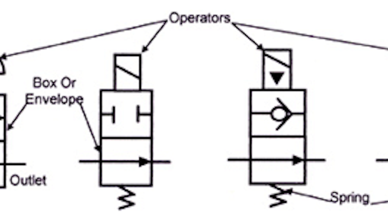
Book 2 Chapter 8 Directional Control Valves Hydraulics Pneumatics
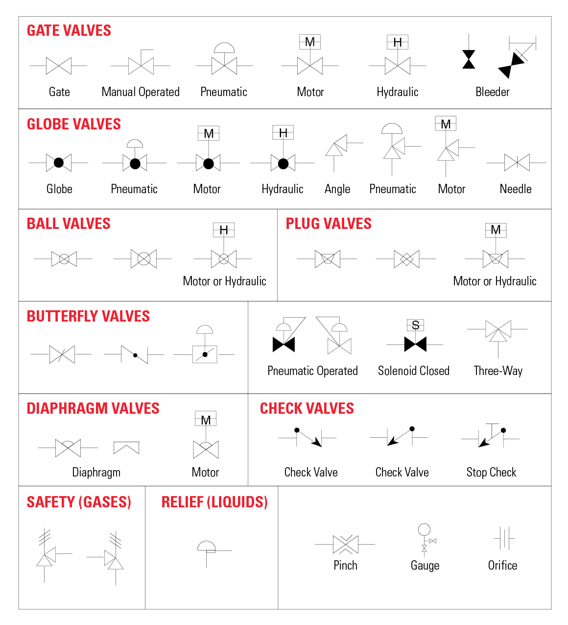
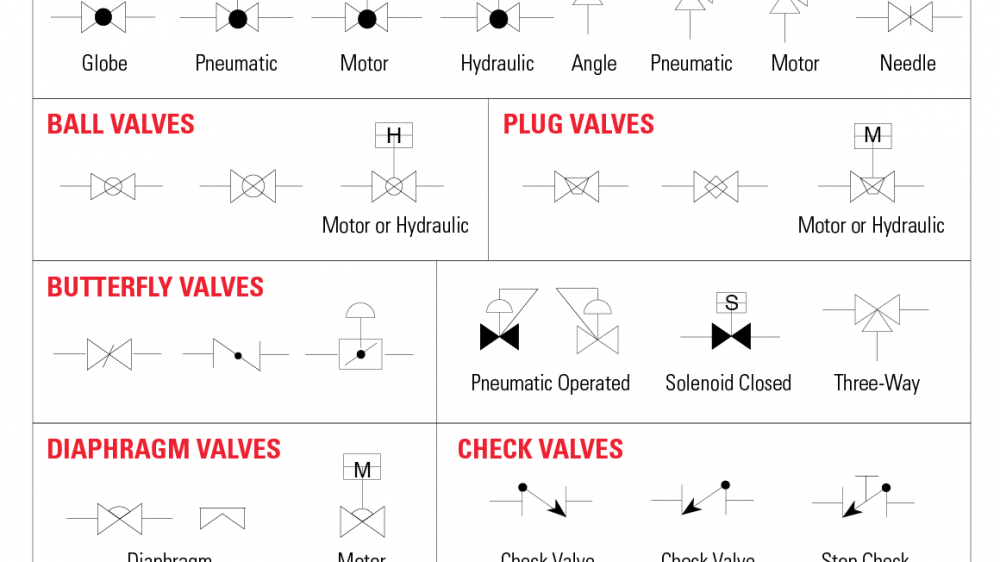
The Most Common Control Valve Symbols On A P Id Kimray
Directional Control Valves Symbols Hydraulic Valve
No Symbol Symbol designation No Symbol Symbol designation 315 Butterfly valve 337 3/2 spring return valve contr by solenoid 316 Gate valve 338 Reducing valve (adjustable) 317 Doubleseated changeover valve 339 On/off valve controlled by solenoid and pilot directional valve and with spring return 318 Suction valve chest 4.

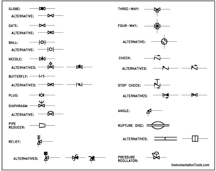
Control valve symbol. Valve Type Valve P&ID Symbols Application Gate Valve Used when a straight flow of fluid and minimum restriction is desired Normally Closed Gate Valve Ball Valve Withstand extreme pressure/temperature and high volume flow Used for high flow capacity Normally Closed Ball Valve Globe Valve Excellent to be used as a control valve due to. Following are schematic symbols for commonly used directional control valves 2way directional control valves A 2way directional valve has two ports normally called inlet and outlet When the inlet is blocked in the atrest condition, as shown in Figure 81, it is referred to as "normally closed" (NC). The final symbol shows a kick down valve which is commonly used to as a pump unloading valve, as they have a lower standby pressures eg energy loss, when open Learn more about sequence valves Proportional pressure control valves.
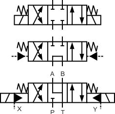
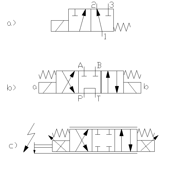
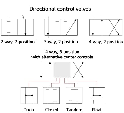
Needle valve symbol Flanged valve symbol Disclaimer The information on this site is for informational purposes only PlumbingHelp, its affiliates and content licensors assume no liability for any inaccurate, incomplete information or the outcome of any project Always consult your local authority regarding plumbing codes for your area. The directional control valve symbol is the most intuitive and selfexplanatory of the symbols Some experience with the directional control valve symbol has already been gained At this point, it is necessary to review the three most common center configurations (Fig 31) for spooltype directional control valves. The ball on seat symbols inside the valve also indicates that this is a low leakage poppet style valve rather than a traditional spool style valve The bottom symbol shows a threeway three position valve that is hydraulically operated This valve also has two end springs to return the spool to the centre position when no pilot signal is available.
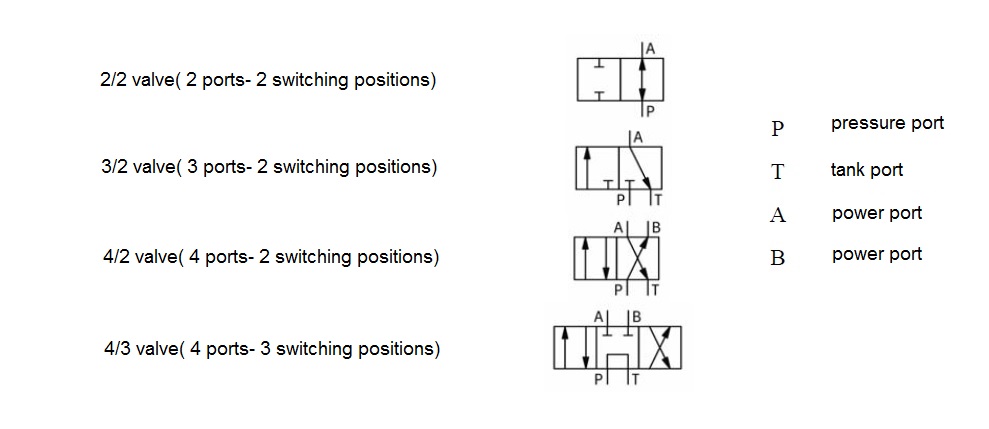
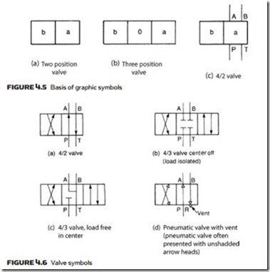
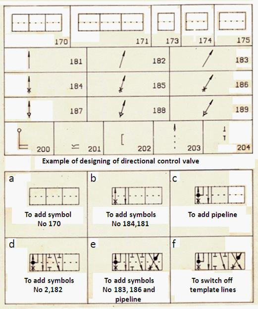
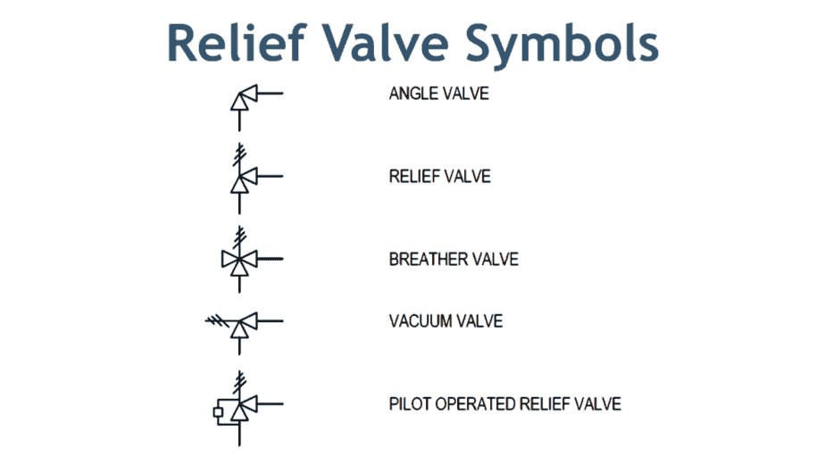
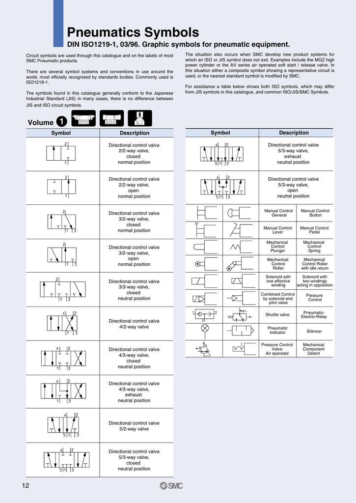
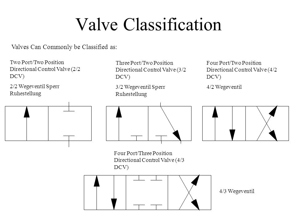
Control is shown by normal actuation symbols in Figure 48b, for example, the spring pushes the valve right, decreasing flow, and pilot pressure pushes the valve left, increasing flow This represents a pressurerelief valve which would be connected into a hydraulic system as shown in Figure 48c. The symbol for directional control valve is made of number of square boxes adjacent to each other depending on the number of positions Connections to the valve are shown on these squares by capital lettersusually they are named only in their normal position and not repeated in other positionsactuation system of the valve is also designated in its symbol. Valve Symbols Valves can have two or more ports and control the flow of the media between those ports The circuit function of the valve describes the different switching states it has For a systematic representation, symbols are used.
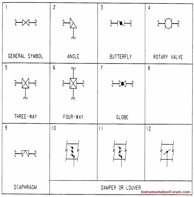
Control Valve Symbols Diaphragm valve A diaphragm valve has a special seal of flexible material to control flow and prevent valve steam leaks DIAPHRAGM VALVE DIAPHRAGM VALVE (GATE SERVICE) (GLOBE SERVICE) (SAUNDERS PAT) (SAUNDERS PAT) Plug valve To control flow through a plug valve, the plug must be turned PLUG VALVE Back pressure valve An automatic back pressure control valve maintains. Everything from ball valve symbols to communication lines are included in a P&ID in order to lay out the proper direction for a process control installation In this article, we highlight some of the most common P&ID valve symbols, process lines, end connections and other vital components. Directional Control Valves Directional control valve (2 ports / 2 positions)Normally closed directional control valve with 2 ports and 2 finite positions Hydraulic Schematic Symbols ShutOff ValveSimplified symbol Accumulators Filters, Water Traps, Lubricators and Miscellaneous Apparatus Filter or Strainer Water Trapwith manual.
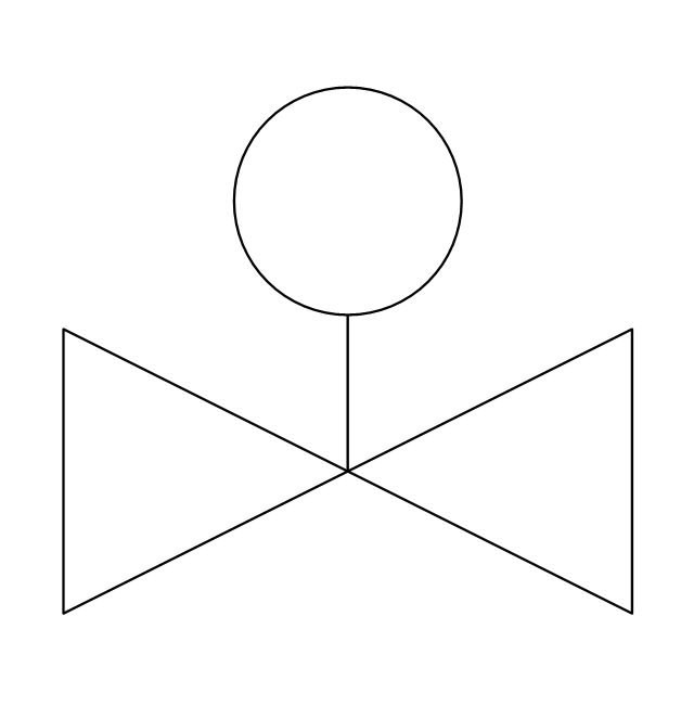
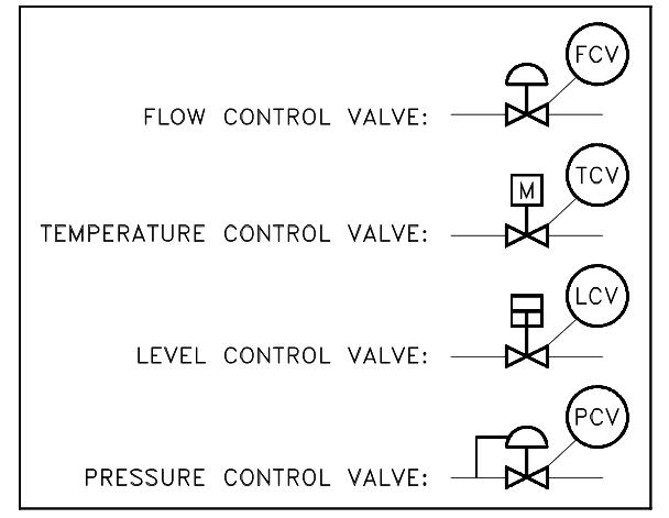
Control is shown by normal actuation symbols in Figure 48b, for example, the spring pushes the valve right, decreasing flow, and pilot pressure pushes the valve left, increasing flow This represents a pressurerelief valve which would be connected into a hydraulic system as shown in Figure 48c. No Symbol Symbol designation No Symbol Symbol designation 315 Butterfly valve 337 3/2 spring return valve contr by solenoid 316 Gate valve 338 Reducing valve (adjustable) 317 Doubleseated changeover valve 339 On/off valve controlled by solenoid and pilot directional valve and with spring return 318 Suction valve chest 4. Control valves are symbolized by combining the appropriate valve symbol and actuator symbol, as illustrated in Figure 2 Control valves can be configured in many different ways The most commonly found configurations are to manually control the actuator from a remote operating station, to automatically control the actuator from an instrument.
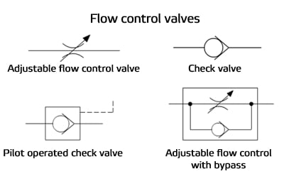
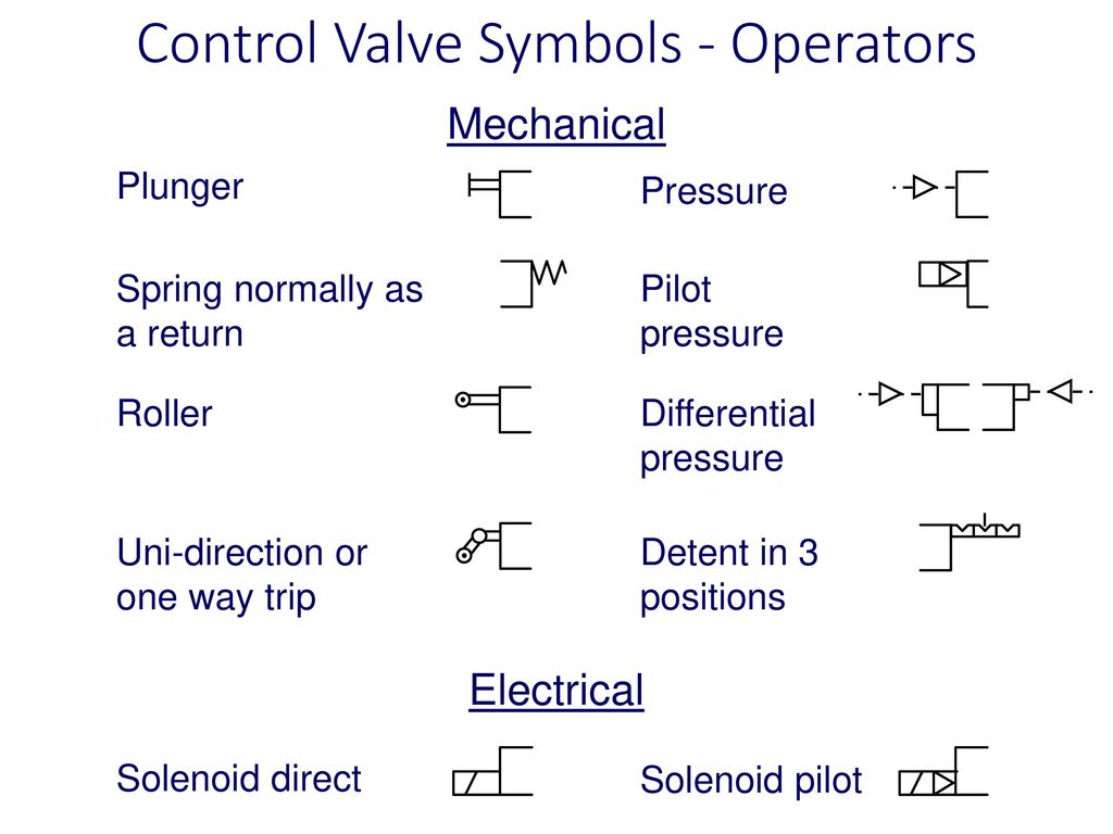
Control Method Operator Symbols for Valves Manual Control General symbol of a valve's manual operator (without showing the control type) Pushbutton Lever Foot pedal Mechanical Valve Control Plunger or tracer Spring (used on one side of a valve to hold it in the normally open or normally closed state). Download over 1,240 icons of valve in SVG, PSD, PNG, EPS format or as webfonts Flaticon, the largest database of free vector icons. The symbol in Figure 149 shows the valve piped for a single flow path Dual flow paths shown in Figure 1410 give twice the flow at the same pressure drop in either flow path Use the throttle valve shown in Figure 1410 to control flow in a bleedoff or bypass circuit, or to control flow to or from a conventional solenoid valve Figure 1410.
In case none of the valves are actuated, the piston rod stays in last position (The symbol at the bottom displays an FRLunit (filter, regulator, lubricator) The functions of cylinders as well as of airpreparation units will be discussed in a later chapter) 3/2way valves 3/2way valves are mostly used to control single acting actuators. Identify the graphic symbols for various types of direction control valves Explain the different applications of direction control valves Explain the working principle of solenoidactuated valves Define valve overlap Evaluate the performance of hydraulic systems using direction control valves 11Introduction. Control Valve PistonOperated Valve Check Valve Back Pressure Regulator Plug or Cock Valve Closed Gate Valve Check Valve 2 Butterfly Valve Angle Valve HandOperated Piping and Instrument Diagram Standard Symbols Detailed Documentation provides a standard set of shapes & symbols for documenting P&ID and PFD, including standard shapes of.
The directional control valve symbol is the most intuitive and selfexplanatory of the symbols Some experience with the directional control valve symbol has already been gained At this point, it is necessary to review the three most common center configurations (Fig 31) for spooltype directional control valves. Legend & Symbol Valves Gate Valve Ball Valve Globe Valve Check Valve Butterfly Valve Hand Control Valve Motor Operated Valve Control Valve c/w Positioner. Basic symbols pressure or return line pilot line two or more functions in one unit flexible hose union cross closed connection direction of movement control valve for use with ls pumps parallel directional control valve for use wffh ls pumps with flow control function fluid treatment breather with filter.
Pneumatic Symbols DIRECTIONAL CONTROL VALVES PROCESS VALVES DESCRIPTION IMAGE DESCRIPTION IMAGE 2/2 way valve, air operated, NC Angle valve, 2way 2/2 way valve, direct operated, NC Ball valve, 2 way 2/2 way valve, pilot operated, NC Ball valve, 3 way, L 3/2 way valve, air operated, NC Ball valve, 3 way, T. Symbols for process valves Valve types/bodies 6 Symbols for valve actuators Actuator types 7 Globe valves, straight through Straight seat 2/2 way 11 Globe valves, multiport Double seat 3/2 way 13 Globe valves, angled design Straight seat 2/2 way 14 Diaphragm valves, straight through 2/2 way 15 Diaphragm valves for tank mounting 2/2 way 16. Control valve, continuosly operated search symbols browse symbols online DXF and DWG viewer view manual video tutorials download ProfiCAD buy ProfiCAD privacy policy contact us subscribe to our newsletter.
Schematic symbols are used to identify and graphically depict the function of fluid power components Recognizing and understanding schematic Valves control the direction and amount of flow while actuators are the work producers such as cylinders and rotary actuators. Valve Symbols Author Department of Veterans Affairs, Office of Acquisition Logistics and Construction, Office of Construction and Facilities Management, Office of Facilities Planning, Facilities Standards Service Subject Standard Detail Created Date 10/18/17 PM. Pressure Control Symbols Hydraulic pressure is controlled through the use of valves valves that open and close at different times to allow fluid to be bypassed from points of high pressure to points of low pressure The basic valve symbol is a square which represents thebypassed from points of high pressure to points of low pressure.
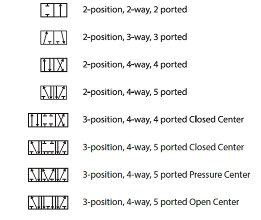
The ISOsymbol contains information concerning the stability of the positions and the reset Directional valves – number of ports and positions The directional valves are described by the numbers of ports in the main valve (excluding pilot ports) and the number of positions the valve can take, number of ports / number of positons. Ball Valve Ball Valve Normally Closed Bleeder Valve Butterfly Valve Check Valve 01 Check Valve 02 Control Valve Diaphragm Valve 01 Diaphragm Valve 02 Electro Hydraulic Valve Excess Flow Valve Flanged Valve 01 Flanged Valve 02 Float Operated Valve Four Way Plug Valve Four Way Valve Gate Valve Gate Valve Closed Gate Valve Hand Operated Gauge Valve Globe Valve. Basic Symbols Square or rectangular block specify a valve position Arrows specify the direction of flow, in this case in one direction, if a line has an arrow at each end then the flow is bidirectional or flow in both directions Symbol for closed port Symbol for two port valve with both ports closed.
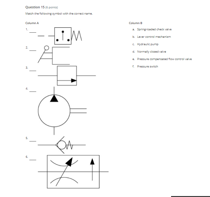
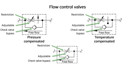
The following symbols are generally in accordance with BS and BS5070 Different Line Types Pipe Support Symbols Symbols for fitting and representations Symbols for Valves Symbols for Valve Actuators Symbols for Instruments Symbols for Flow Instruments Instrument Indentifiers. The first symbol in Figure 2 depicts the simplified version of pressure and temperature compensated flow control This symbol comprises the orifice arcs, the variable arrow and reverseflow check valve, just as with standard flow control However, the addition of the upward facing arrowhead tells us it is pressure compensated. The SP53 committee in developing ISAS53, "Graphic Symbols for Distributed Control/Shared Display Instrumentation, Logic and Computer Systems" The key elements of ISAS53 have.
2 interlock number and proper symbol (dcs or plc) will be shown on process p&id 3 for valves located in pits with extended valve stems / actuators, limit switch and positioner will be located outside the pits 4 safety solenoid valve (sy) is to trip the valve to its failure position 5. 8 2way valves are seldom used in air logic circuits but on those occasions where a 2way valve is needed the 3way valve symbol can be used, with an appropriate notation as to its function in the circuit such as shown The 3way NO valve is the same regardless of how it is oriented or whether the outlet is to the right or left Free. The ISOsymbol contains information concerning the stability of the positions and the reset Directional valves – number of ports and positions The directional valves are described by the numbers of ports in the main valve (excluding pilot ports) and the number of positions the valve can take, number of ports / number of positons.
Following are schematic symbols for commonly used directional control valves 2way directional control valves A 2way directional valve has two ports normally called inlet and outlet When the inlet is blocked in the atrest condition, as shown in Figure 81, it is referred to as "normally closed" (NC). The way to decipher a direction control valve symbol is as follows Every square box indicates one valve position The central position is a neutral position and various neutral positions are available depending upon the application All ports closed will increase the system pressure to the maximum – actuating the pressure relief valve. The way to decipher a direction control valve symbol is as follows Every square box indicates one valve position The central position is a neutral position and various neutral positions are available depending upon the application All ports closed will increase the system pressure to the maximum – actuating the pressure relief valve.
2 interlock number and proper symbol (dcs or plc) will be shown on process p&id 3 for valves located in pits with extended valve stems / actuators, limit switch and positioner will be located outside the pits 4 safety solenoid valve (sy) is to trip the valve to its failure position 5. Download over 1,240 icons of valve in SVG, PSD, PNG, EPS format or as webfonts Flaticon, the largest database of free vector icons. Valve Type Valve P&ID Symbols Application Gate Valve Used when a straight flow of fluid and minimum restriction is desired Normally Closed Gate Valve Ball Valve Withstand extreme pressure/temperature and high volume flow Used for high flow capacity Normally Closed Ball Valve Globe Valve Excellent to be used as a control valve due to.
Needle valve symbol Flanged valve symbol Disclaimer The information on this site is for informational purposes only PlumbingHelp, its affiliates and content licensors assume no liability for any inaccurate, incomplete information or the outcome of any project Always consult your local authority regarding plumbing codes for your area. Schematic symbols are used to identify and graphically depict the function of fluid power components Recognizing and understanding schematic Valves control the direction and amount of flow while actuators are the work producers such as cylinders and rotary actuators. Control valve symbol is incorrect and the substitution palette shows instrument symbols Note This may occur after making a substitution of the valve body symbol.
Control valves are symbolized by combining the appropriate valve symbol and actuator symbol, as illustrated in Figure 2 Control valves can be configured in many different ways The most commonly found configurations are to manually control the actuator from a remote operating station, to automatically control the actuator from an instrument, or both. It is a modification of a generic valve symbol by inserting a vertical line between two triangles Three symbols shown below are the gate valve symbols used in isometric drawings The first is for buttwelding ends, second is for flanged end valve and the third one is for socket end connection Globe Valve Symbol. Symbol Via electric stepper motor Via solenoid, e g with two counteracting solenoids Nonreturn valve without spring Quick exhaust valve Shuttle valve Oneway flow control valve, adjustable Nonreturn valve with spring Dualpressure valve Via solenoid or manual override and pilot valve Flow control valve Nonreturn valve Connection.
Commonly used P&ID symbols ( Piping and Instrumentation Diagram symbols) for control valve actuators Note that they may differ slightly from one project to another Control valve assembly Manual (handwheel) Diaphragm actuator {adinserter 1} Balanced diaphragm actuator Motor actuator {adinserter 1}. The Standard Control Valve Symbol Each P&ID has its own legend that identifies the symbols for the various equipment While there is some variation, examples of the standard symbols for control valves are in the PDF below Symbols include gate valve symbol;. The final symbol shows a kick down valve which is commonly used to as a pump unloading valve, as they have a lower standby pressures eg energy loss, when open Learn more about sequence valves Proportional pressure control valves.
Ball Valve symbol Normally Closed Ball Valve symbol Globe Valve symbol Butterfly Valve symbol Check Valve symbol Plug Valve symbol Needle Valve symbol Self Draining Valve symbol Integrated Block and Bleed Valve symbol Auto Recirculation Valve symbol Angle Valve symbol Angle Globe Valve symbol 3way Valve symbol Y Blowdown Valve symbol Angle Blowdown Valve symbol. ISO and ANSI schematic symbols for pressurecompensated flow control valves The desired flow rate is set on the variable orifice by adjusting the passthrough area of the orifice This adjustment can be made manually by means of a knob, screw or lever on the valve or remotely with electronic signals to a solenoid actuator attached to the. The symbols above are all of a directional control cartridge poppet valve The top left image has a 11 ratio This is indicated by the straight nature of the spool/poppet body.
Directional air control valves are the building blocks of pneumatic control Pneumatic circuit symbols representing these valves provide detailed information about the valve they represent Symbols show the methods of actuation, the number of positions, the flow paths and the number of ports Here is a brief breakdown of how to read a symbol. Pneumatic Symbols DIRECTIONAL CONTROL VALVES PROCESS VALVES DESCRIPTION IMAGE DESCRIPTION IMAGE 2/2 way valve, air operated, NC Angle valve, 2way 2/2 way valve, direct operated, NC Ball valve, 2 way 2/2 way valve, pilot operated, NC Ball valve, 3 way, L 3/2 way valve, air operated, NC Ball valve, 3 way, T.

Simple Set Of Shut Off And Control Valves Vector Symbols And Royalty Free Cliparts Vectors And Stock Illustration Image

Control Valve With Pneumatic Actuator

Pressure Control Valve Symbol Icons Download Free Vector Icons Noun Project
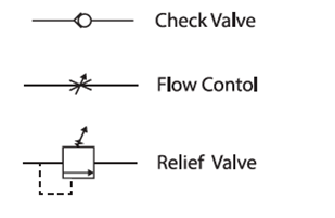
Common Symbols Used In Pneumatic Systems And Instrumentations Learning Instrumentation And Control Engineering
Symbols And Parts Introduction Gaz Khodro Sepehr

What S The Difference Between Hydraulic Circuit Symbols Machine Design

Gate Valve Symbol Page 1 Line 17qq Com

China Electro Hydraulic Directional Control Valve Hydraulic Control Valves Hoyea

Control Valves In P Id Control Valves Instrumentation Forum
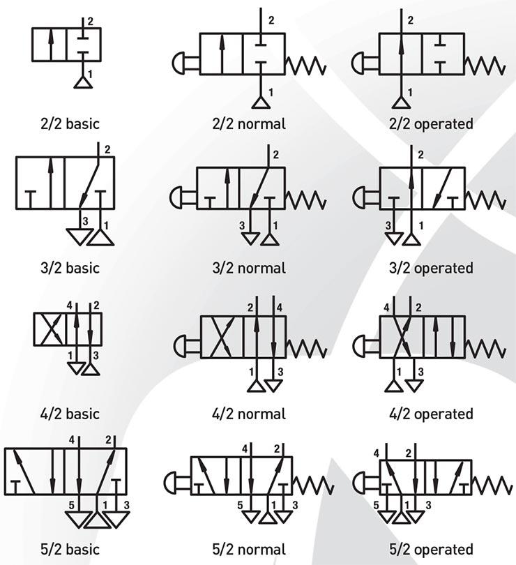
Control Valves Port Marking And Pneumatic Symbols Part2 Jpg Digramatic Representations Albums Mechanical Engineering

Valve Symbols Flow Control Norway As
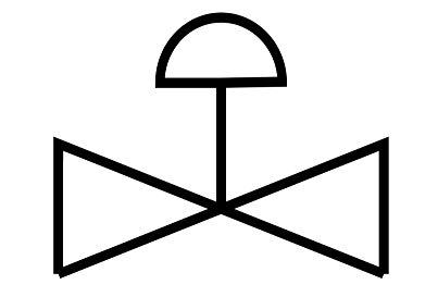
Control Valve Stroke Test Procedure Instrumentationtools
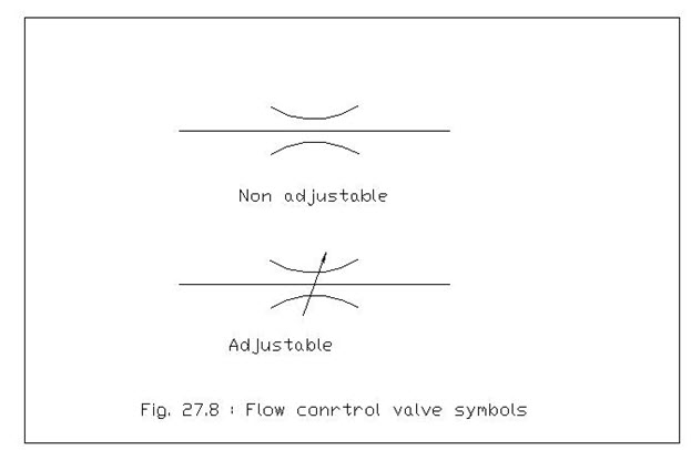
Hd C Lesson 29 United States Of American Standards Institute Usasi Graphical Symbols

File Symbol Pressure Control Valve Adjustable Svg Wikipedia

Pressure Control Upstream And Downstream

Shuttle Valve An Overview Sciencedirect Topics
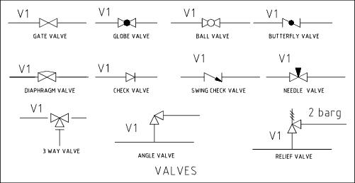
Solenoid Valve Symbols
Control Valve Symbol Icon Royalty Free Vector Image

Pin On Pneumatic

Tip 14 Go With The Flow Control Hydraulics Pneumatics
Solved Question 15 6 Points Match The Following Symbol Chegg Com
Directional Valve Symbols

Hydraulics Flow Control Valve Hydraulic Tutor Stuffworking Com
Pneumatic Valve Symbols Flow Control Valves

China Electrical Operated Directional Control Valve Hydraulic Control Valve Hoyea
Control Valves Graphic Symbols Hydraulics And Pneumatics
Tip 18 Get Control Of Yourself Hydraulics Pneumatics

Flow Control Valves Hydraulic Symbology 4

Process Diagram Symbols Lowflow Valve Fractional Flow Control Valves Regulators

Hydraulic Symbols Introduction
Reading Fluids Circuit Diagrams Hydraulic Pneumatic Symbols
Introduction To Control Valves Symbols

Hsf Oilquip

Hydraulic Symbols Part E Www Motioninstituteonline Com Youtube

Check Valve Control Valves Directional Control Valve Hydraulic Pump Symbol Angle Ball Valve Png Pngegg
Synthesis Of Hydraulic Circuits Library Of Standard Graphic Symbols Of Hydraulic Elements

A Guide To Common Hydraulic Symbols Engineeringclicks
Can Anyone Show Me What A Proportional Valve Schematic Symbol Looks Like

Hydraulic Symbols Fluid Power Engineering Eng Tips
Reading Fluids Circuit Diagrams Hydraulic Pneumatic Symbols
Valve Symbols In P Id Ball Valve Relief Valve And More

Solenoid Valve Symbols
Common Symbols Used In Pneumatic Systems And Instrumentations Learning Instrumentation And Control Engineering

File Control Valve Svg Wikimedia Commons

Hydraulic Reducing Valve Symbols
Control Valve Symbols Control Valves Instrumentation Forum

Flow Control Valves One Way Flow Control Valve Adjustable Valves Fluid Power Pneumatics Symbols Services Festo Didactic

Piping Coordination System Mechanical Symbols For Isometric Drawings
Directional Control Valves Symbols Hydraulic Valve
Control Valve Symbol

File Symbol Flow Control Valve Svg Wikimedia Commons
Pneumatics Symbols
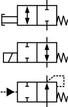
Directional Valve Symbols

What Are Hydraulic Flow Control Valves And How To Test Finotek
Pressure Control Valve Symbol Icon Royalty Free Vector Image
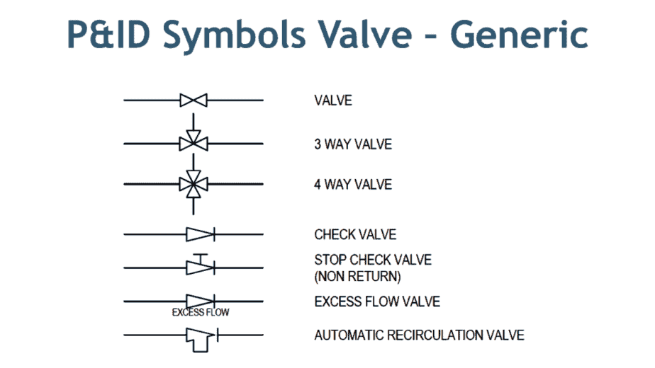
Valve Symbols In P Id Ball Valve Relief Valve And More
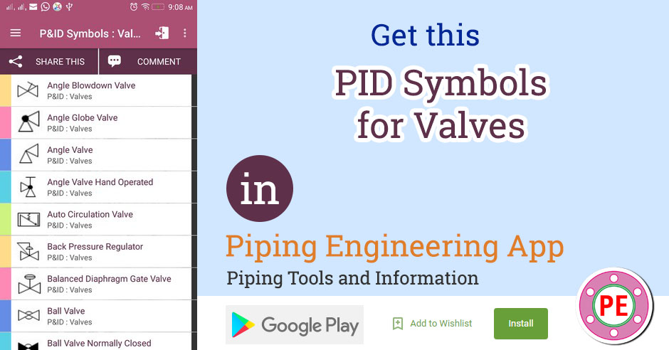
P Id Symbols For Valves The Piping Engineering World

Common P Id Symbols Used In Developing Instrumentation Diagrams Learning Instrument Piping And Instrumentation Diagram Control Engineering Electrical Symbols

Fire Equipment Signs Photoluminescent Rigid Pvc Sprinkler Control Valve Symbol 6153gmpr
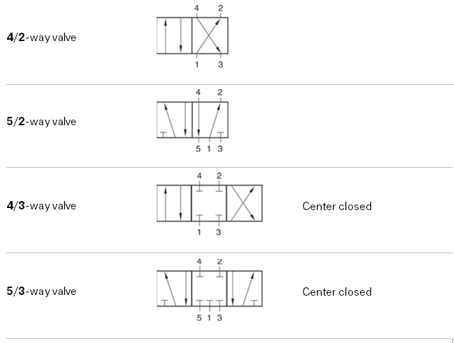
Iso Schemes Of Directional Control Valves
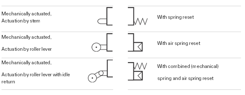
Iso Schemes Of Directional Control Valves

Valves Symbols

Flow Control Valve
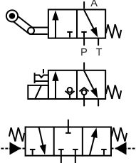
Directional Valve Symbols
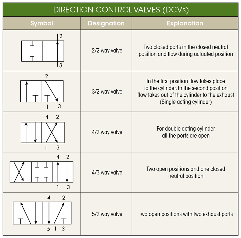
What S The Difference Between Hydraulic Circuit Symbols Machine Design

Valve Symbols Flow Control Norway As

Directional Control Valves Directional Control Valves Classification By Port Position Count Hydraulic Schematic Troubleshooting
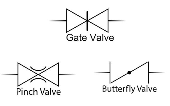
Valve Symbol Saba Dejlah
The Most Common Control Valve Symbols On A P Id Kimray
Fluid Power Symbols Ppt Video Online Download

Proportional Flow Control Valves Archive Weber Hydraulik

Symbols For Hydraulic Pressure Control Valves
Control Valve Symbol High Res Stock Images Shutterstock

Valves Which Control The Direction Of The Flow Of The Compressed Air Spool Valves

Flow Control Valves Hydraulic Symbology 4

Control Valve Symbols Chemical Engineering Blog Facebook
Reading Fluids Circuit Diagrams Hydraulic Pneumatic Symbols
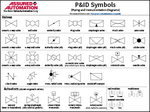
P Ids Piping Instrumentation Diagrams And P Id Valve Symbol Library Assured Automation

Control Valve 5 3 Valve Pneumatic Symbols Cad Block And Typical Drawing
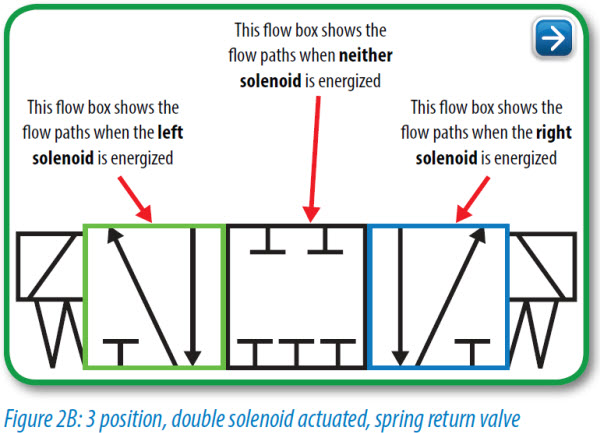
Pneumatic Circuit Symbols Explained Library Automationdirect

Solenoid Valves Discrete Control System Elements Automation Textbook

Control Valves Components Selection Types Symbols Installation What Is Piping All About Piping Engineering
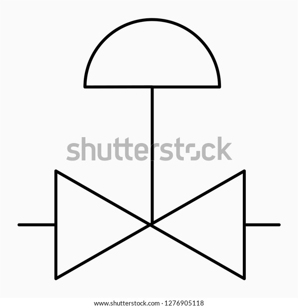
Control Valve Symbol Shut Off Faucet Stock Vector Royalty Free

Hydraulic Symbology 3 Pressure Valves

Flow Control Valves Hydraulic Flow Control Valves Hydraulic Schematic Troubleshooting
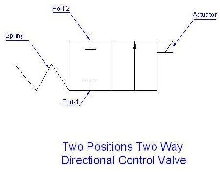
Glossary Of Iso Hydraulic Schematic Symbols And Their Meanings Bright Hub Engineering
Design Elements Valves And Fittings Valves Vector Stencils Library Interior Design Piping Plan Design Elements Piston Valve Symbol
Flow Control Valve Electronic Symbol Hydraulics Png 1024x415px Flow Control Valve Area Black Black And White
Piping And Instrumentation Symbols Instrumentation Tools

Control Valves Typical P Id Arrangement Enggcyclopedia
Piping And Instrumentation Symbols Instrumentation Tools

Solenoid Valve Symbols


