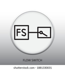
Flow Switch Symbol

Energy Harvesting Applications Proximity Switch Symbol
Q Tbn And9gcsqciqh4cpkm H0ey2zivgeg8lfjzvxtztnlijc6ksmu9mmdp1r Usqp Cau

Chapter 4 Iso Symbols And Glossary Part 3 Hydraulics Pneumatics
Process Flow Diagram Symbols
Hydraulic Symbology 301 Electrical And Electronic Symbols

Diagram Mcdonnell Miller Flow Switch Symbol Wiring Diagram Fs51 Full Version Hd Quality Diagram Fs51 Gspotdiagram Pisciculture Saintcesaire Fr
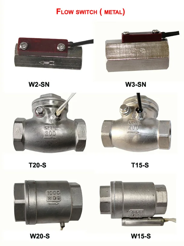
The Taco Industrial Flow Switch (IFS) starts or stops electronically operated equipment when a flow or no flow condition occurs The IFS can be used in 1'' to 8'' liquid flow lines, carrying water or any nonhazardous fluid not harmful to brass, stainless steel or EPDM It is used in a wide variety of applications including heating systems, domestic water boosters, process work, water systems.
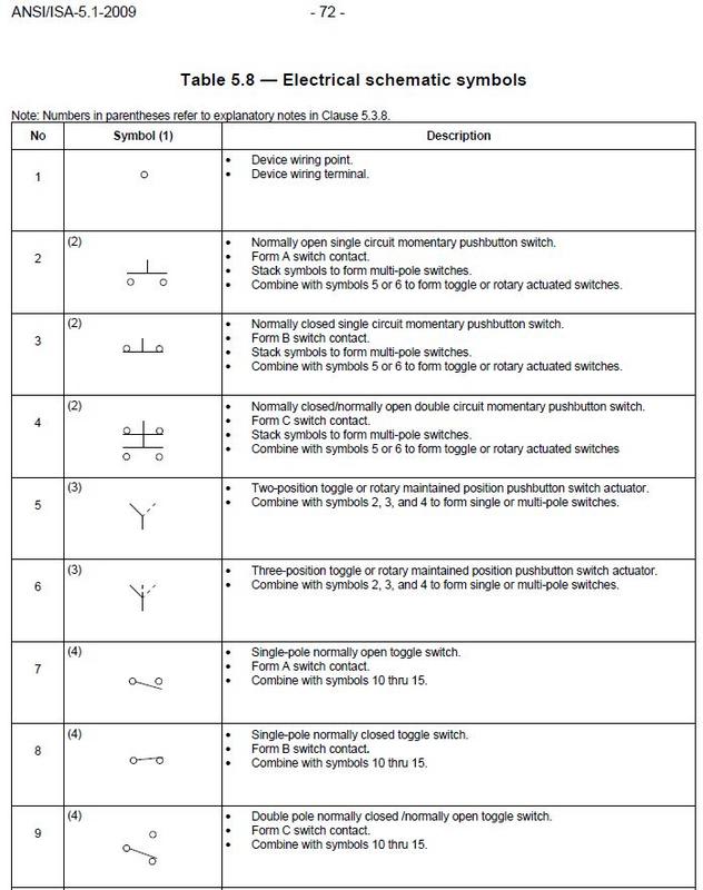
Flow switch symbol. Australian / New Zealand electrical symbols for drafting. Switch and single receptacle a = circuit designation b = device type designation disconnect switch a = type, refer to disconnect schedule smoke detector a = type i = ionization p = photoelectric d = duct detector fire sprinkler f = flow switch t = tamper switch multi conductor cables k/2/c#16s k (where indicated) = number of pairs. Series FS43D flow switch Series AF3D flow switch Series FS5D flow switch Make one circuit andbreak one circuit with no common terminals Series 5 & 6 switches 14 AirFlwSwtchs1141• 3/6/07 213 PM Page 117 S w i t ch Operation No 2 Switch Used on McDonnell No 472,.
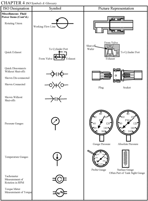
Our products SMC has a range of 12,000 basic models and over 700,000 variations to respond to daytoday automation needs Our experts are always on hand to provide the necessary technical support and guidance. SPST Toggle Switch Disconnects current when open SPDT Toggle Switch Selects between two connections Pushbutton Switch (NO) Momentary switch normally open Pushbutton Switch (NC) Momentary switch normally closed DIP Switch DIP switch is used for onboard configuration SPST Relay. The switch symbol typically refers to a single pole switch which is most commonly wall mounted and found in all areas of the home 3Way Switch the 3way switch symbol is used to describe a pair of light switches which are found in areas such as a hallway or stairway where a 3way switch is located at opposite ends.
Symbol Description Aquastat Flow switch Pressure switch Water hammer arrester Pressure gauge with gauge cock Thermometer (specify type) Automatic air vent Valve in riser (type as specified or noted) Riser down (elbow) Riser up (elbow) Air chamber Rise or drop Branch—top connection. ABOUT KOBOLD USA For decades, KOBOLD has been a world leader in process measurement and control solutions We offer one of the industry’s broadest lines of sensors, switches and transmitters to measure and control flow, pressure, level and temperature. Series FS43D flow switch Series AF3D flow switch Series FS5D flow switch Make one circuit andbreak one circuit with no common terminals Series 5 & 6 switches 14 AirFlwSwtchs1141• 3/6/07 213 PM Page 117 S w i t ch Operation No 2 Switch Used on McDonnell No 472,.
Flow switches are mechanical devices used in controlling the flow of air, steam, or liquid A flow switch operates by conveying a trip motion (relay, reed switch, paddle) to another machine within the system, usually a pump The trip signal will indicate to the pump to turn on or turn off. Let’s start with the most basic float switch a twowire, singlepole, singlethrow float switchThe rising action of the float can either close (ie, turn on) a “Normally Open” circuit, or it can open (turn off) a “Normally Closed” circuitInstallation scenarios might include a Normally Open float switch turning on a pump to empty a tank (Control Schematic 2), or a Normally Closed. The flow switch can easily be tested without having to disconnect the electrical leads or dismantling the switch A simple multimeter is all you need to effectively troubleshoot your flow safety device Contact ATI of New York The experts at Applied Technologies of New York specialize in all things boiler.
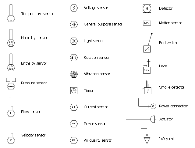
The principle of operation is quite simple Air flow exerts a force on a paddle, actuating a dusttight SPDT micro switch The switching point may be adjusted continuously within a wide range, making the LPS useful in a wide variety of applications The flow switch is factory set to switch at 195 FPM. Let’s start with the most basic float switch a twowire, singlepole, singlethrow float switchThe rising action of the float can either close (ie, turn on) a “Normally Open” circuit, or it can open (turn off) a “Normally Closed” circuitInstallation scenarios might include a Normally Open float switch turning on a pump to empty a tank (Control Schematic 2), or a Normally Closed. Symbols of Electronic Sensors The sensors are transducers and electronic detectors activated by the energy delivered by a system and that in turn deliver another type of energy to another different systemThe transformed energy may be of physical, chemical or biological origin.
Their application areas range from simple monitoring tasks as an on/off switch to precise digital flow rate measurements Use the “Select By Application” tool to narrow your search for a flow sensor based on media type, and read more about the underlying measuring principles and technology of a sensor group by accessing the orange “Learn. The mechanism of a switch may be operated directly by a human operator to control a circuit (for example, a light switch or a keyboard button), may be operated by a moving object such as a dooroperated switch, or may be operated by some sensing element for pressure, temperature or flow A relay is a switch that is operated by electricity. Flow Sensors symbols for use in electrical, pneumatic and hydraulic schematic diagrams Available in SVG, PNG, JPG, DXF & DWG formats.
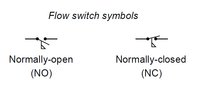
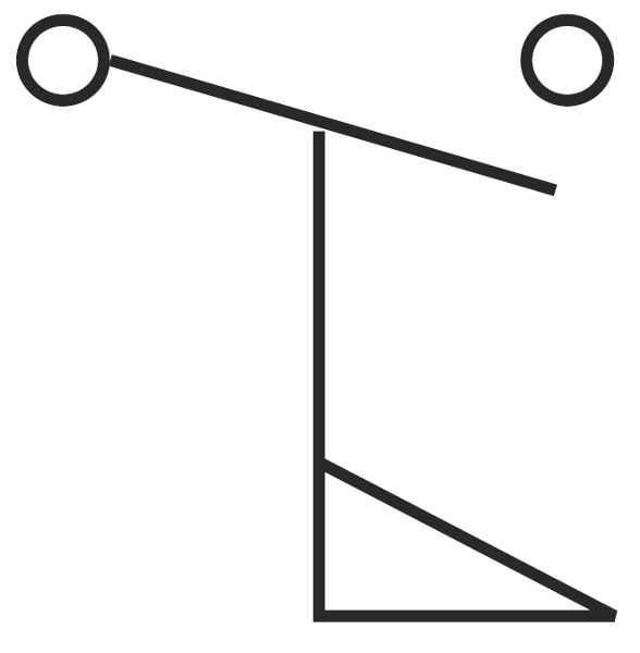
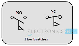
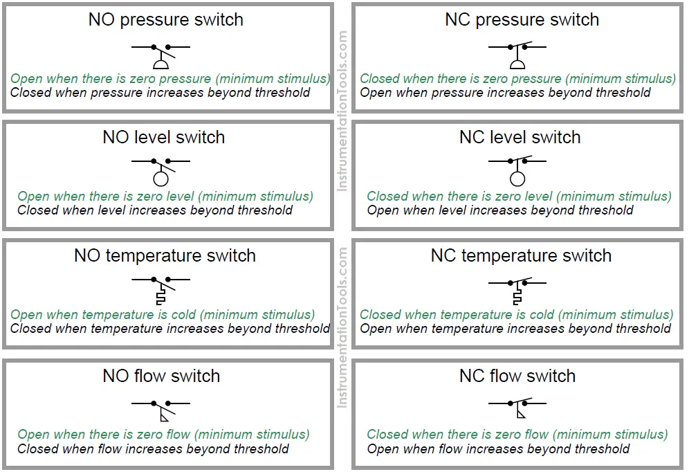
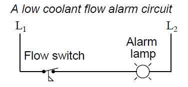
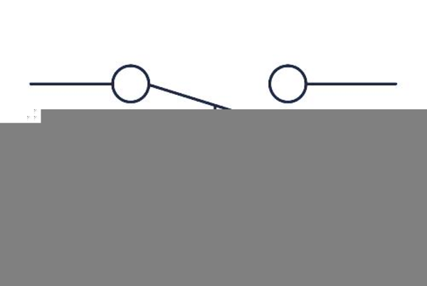
Switch and single receptacle a = circuit designation b = device type designation disconnect switch a = type, refer to disconnect schedule smoke detector a = type i = ionization p = photoelectric d = duct detector fire sprinkler f = flow switch t = tamper switch multi conductor cables k/2/c#16s k (where indicated) = number of pairs. Flow Switches A flow switch is one detecting the flow of some fluid through a pipe Flow switches often use paddles as the flowsensing element, the motion of which actuates one or more switch contacts The symbol for a flow switch is shown below. Flow switches are used for the display and monitoring of the flow of liquid and gaseous media The instruments feature a high switching accuracy and functional safety, low switch hysteresis and continuous switch point setting by the operator To do this, select the desired language using the flag symbol The maximum number of entries was.
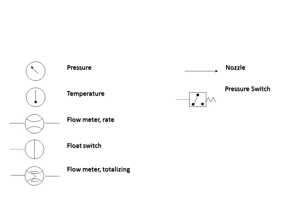
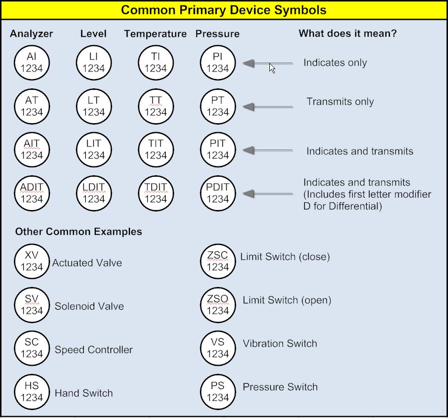
FS925 (general) FS926 (low flow) precision flow switches for gases & liquids datasheet (PDF) FS925 FS926 manual (PDF) Gems Sensors Reed switch protection (PDF). F = flow rate, P = pressure, T = temperature, L = level 2nd letter is a modifier D = differential, F = ratio simply omit if no modifiers apply 3rd indicates passive/readout function A = alarm, R = record, I = indicator, G = gauge 4th – active/output function C = controller, T = transmit, S = switch, V = valve 5th is the function modifier. SystemActivitiesStatementsFlowSwitch A Flowchart specific activity that splits the control flow into three or more branches, out of which a single one is executed based on a specified condition Cases All the possible sequences out of which a single one is executed, based on its match with the pr.
Flow switches are mechanical devices used in controlling the flow of air, steam, or liquid A flow switch operates by conveying a trip motion (relay, reed switch, paddle) to another machine within the system, usually a pump The trip signal will indicate to the pump to turn on or turn off. Electrical symbols & electronic circuit symbols of schematic diagram resistor, capacitor, inductor, relay, switch, wire, ground, diode, LED, transistor, power. Horizontal Symbol Vertical Symbol Description HPS11 VPS11 Pressure Switch, Normally Open HPS12 VPS12 Pressure Switch, Normally Closed HTS11 VTS11 Temperature Switch 1, Normally Open HTS12 VTS12 Temperature Switch 1, Normally Closed HTS11S18 VTS11S18 Temperature Switch 2, Normally Open HTS12S18 VTS12S18 Temperature Switch 2, Normally Closed HTS11S74 VTS11S74 Temperature Switch 3, Normally Open.
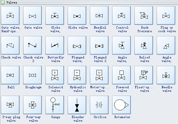
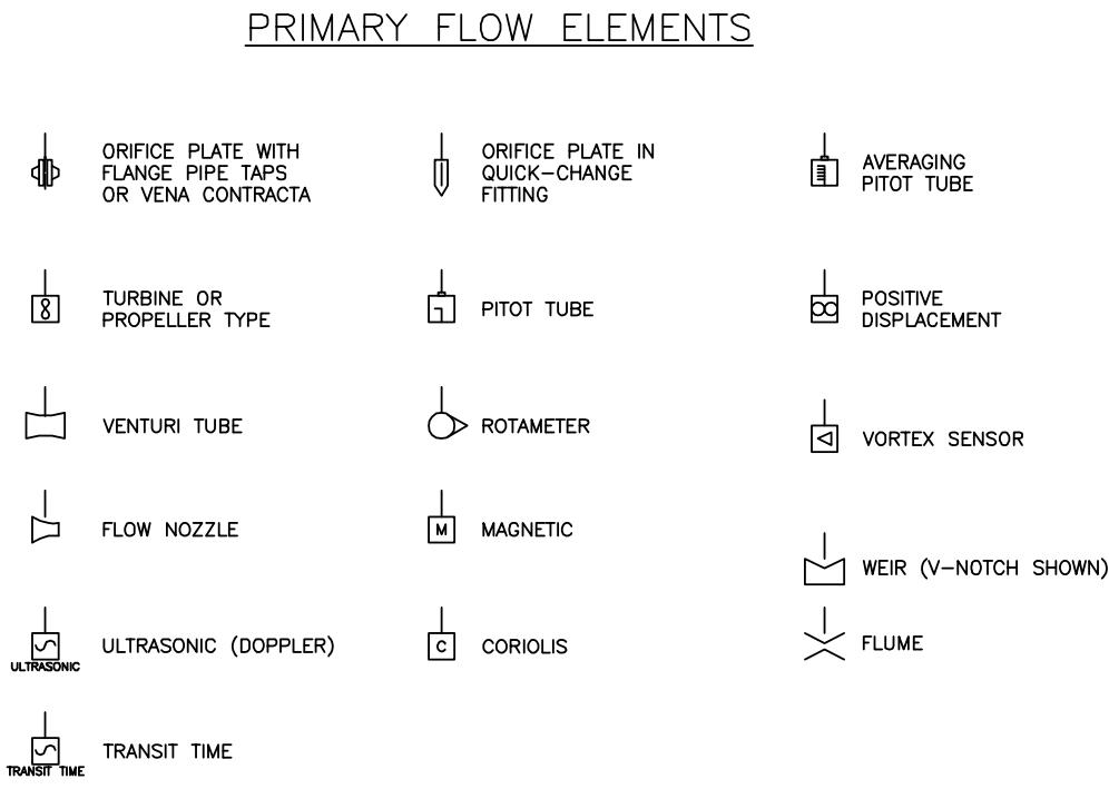
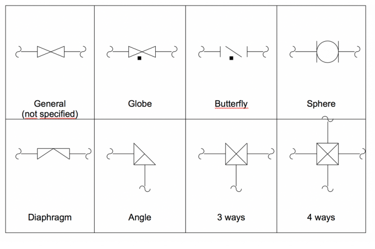
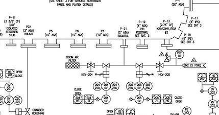
The direction of flow is indicated by an arrowhead at the end of the line where it meets the next component as well as at every 90 degree turn Type of Valve The type of valve is represented by adding a shape to the center where the points touch Shown here are P&ID symbols for the most common valve types. Horizontal Symbol Vertical Symbol Description HPS11 VPS11 Pressure Switch, Normally Open HPS12 VPS12 Pressure Switch, Normally Closed HTS11 VTS11 Temperature Switch 1, Normally Open HTS12 VTS12 Temperature Switch 1, Normally Closed HTS11S18 VTS11S18 Temperature Switch 2, Normally Open HTS12S18 VTS12S18 Temperature Switch 2, Normally Closed HTS11S74 VTS11S74 Temperature Switch 3, Normally Open. Paddle flow switches or vane sensors with an electrical contact output are at a specific flow rate Dwyer flow switches are economical and reliable Applications include proof of boiler flow, air conditioning, controlling of dampers according to flow, and protecting pumps, motors and other equipment against low or no flow.
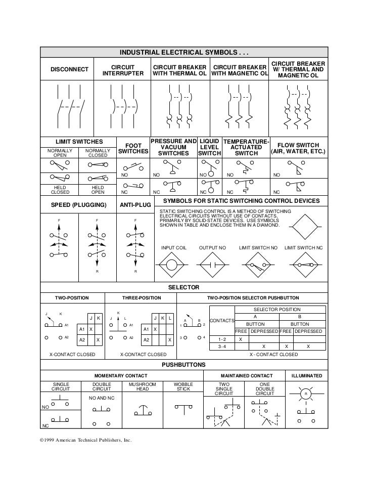
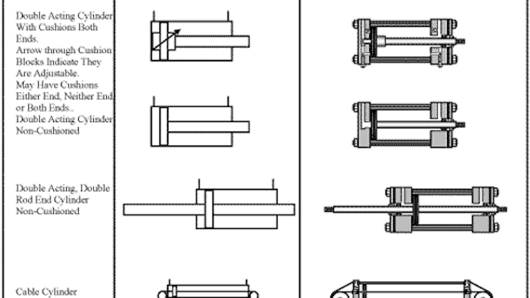
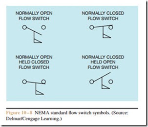
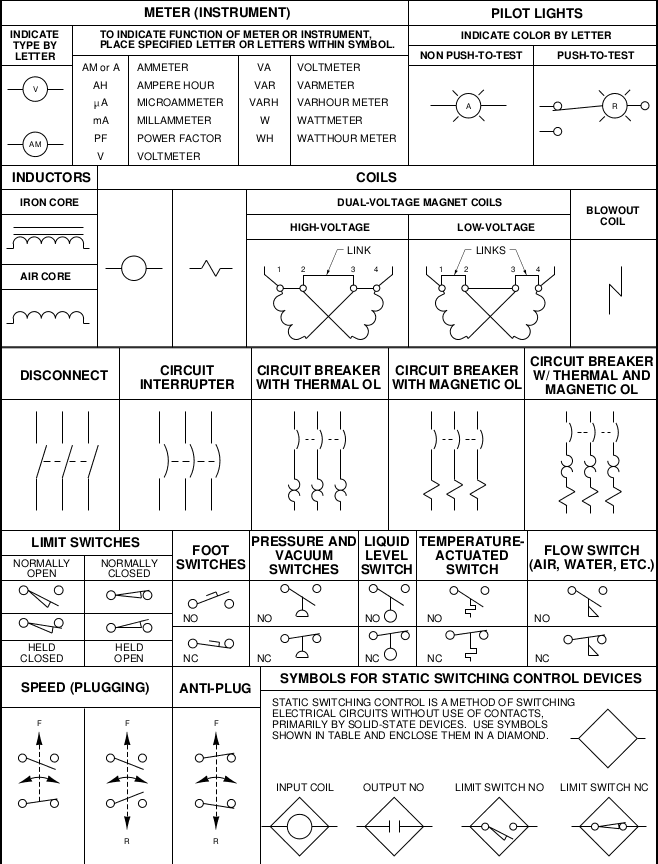
These graphic symbols are the ones used most often on ladder diagrams for fluid power electrical control circuits They are standard JIC (Joint Industrial Council) symbols as approved and adopted by the NMTBA (National Machine Tool Builders Association). 28 Each symbol is drawn to show normal, at rest, or neutral condition of component unless multiple diagrams are furnish shown various phases of circuit operation Show an actuator symbol for each flow path condition possessed by the component 29 An arrow through a symbol at approximately 45. The symbol for the switch looks like a dollar sign and is connected to the receptacle with a line This symbol, the circle with four lines protruding from each pole, is usually used to represent a ceiling mounted incandescent ˜xture The note “A13” indicates the ˜xture is supplied by panel A, circuit breaker number 13.
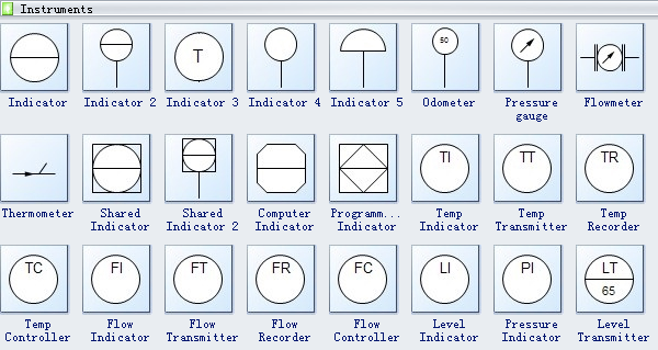
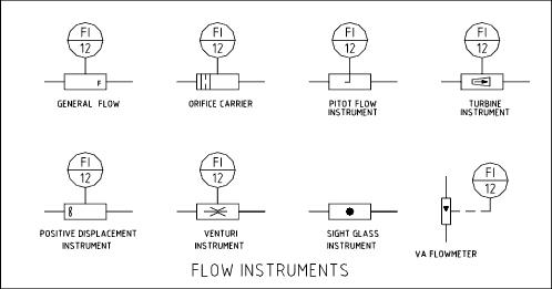
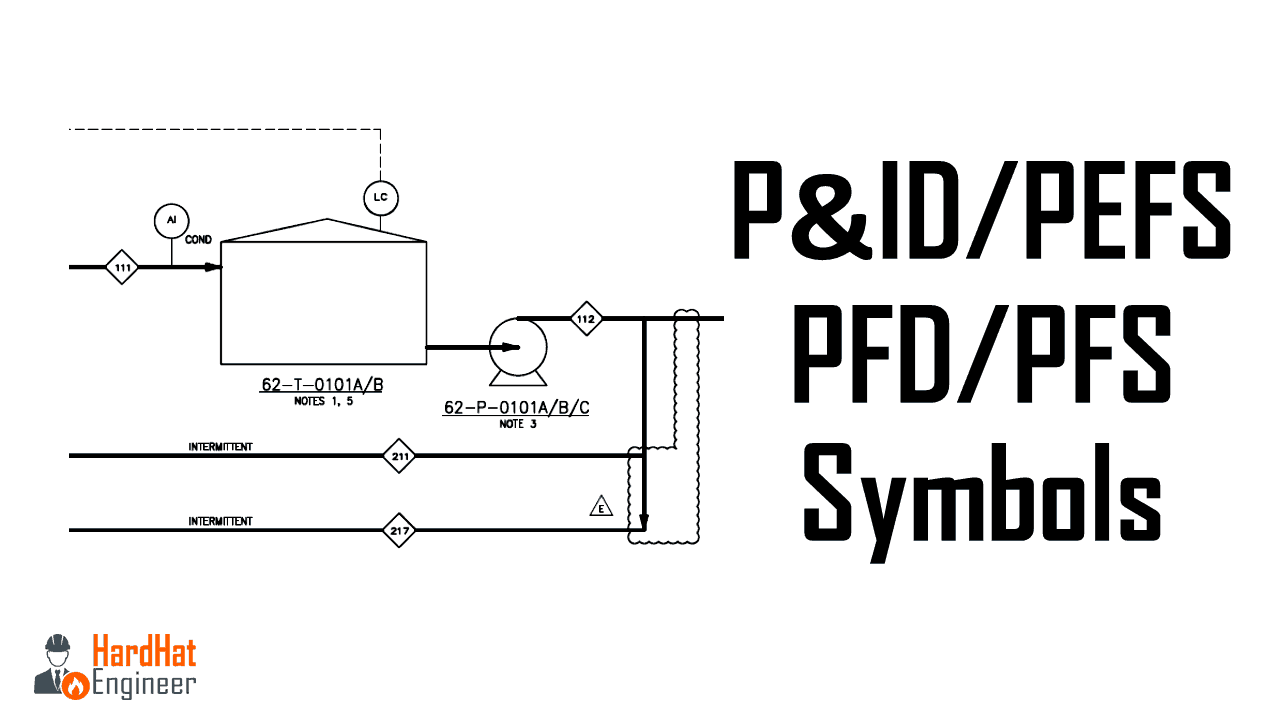
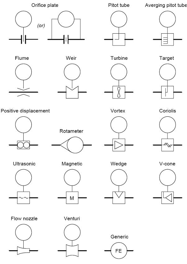
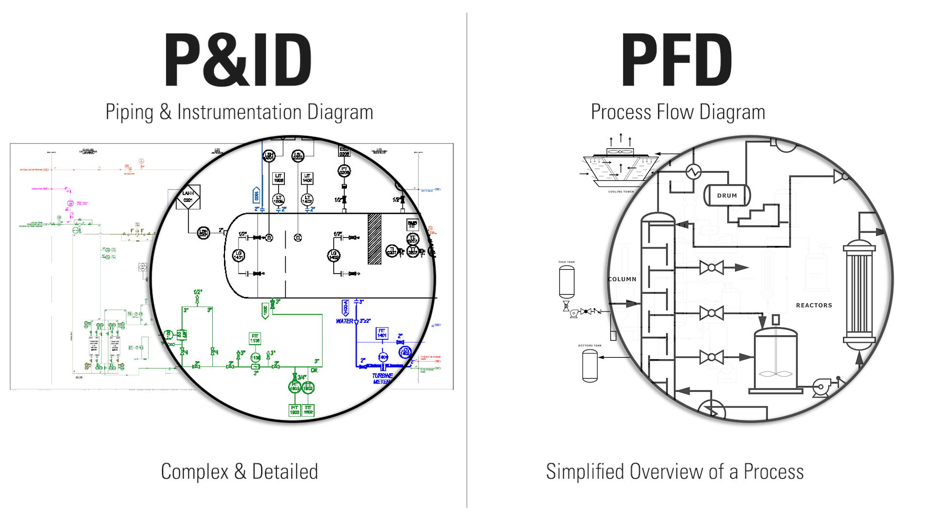
The flow switch can easily be tested without having to disconnect the electrical leads or dismantling the switch A simple multimeter is all you need to effectively troubleshoot your flow safety device Contact ATI of New York The experts at Applied Technologies of New York specialize in all things boiler. Flow Switch Sensors with an electrical contact output at a specific flow rate have different types of switches, which are paddle, thermal, piezo, and shuttle/piston Flowmeters Flowmeters indicate flow rate The different sensors include dial, inline, ultrasonic, orifice plate, totalizing meters, variable area, venturi, or with switch output. PFD is a Process Flow Diagram P&ID is a Process or piping & Instrument Diagram PFS means Process Flow Scheme and PEFS means Process Engineering Flow Scheme Here, I have tried to cover symbols that regularly used on the P&ID and PFD There are other symbols also you can check the full list of the symbol by visiting this link I advised you.
Flow switch used to activate a device when flow stops When the decreasing operating flow is reached or stops the common (black wire) and the normally open (red wire) contacts open, while the common (black wire) and the normally closed (blue wire) contacts close Flow switch is used to activate a device when flow starts. In order to better understand this concept, we will consider a simple application of a flow switch a switch built to actuate when a sufficient rate of fluid flows through a pipe A flow switch is built to detect fluid flow through a pipe In a schematic diagram, the switch symbol appears to be a toggle switch with a “flag” hanging below. Symbols of Electronic Sensors The sensors are transducers and electronic detectors activated by the energy delivered by a system and that in turn deliver another type of energy to another different systemThe transformed energy may be of physical, chemical or biological origin.
PFD is a Process Flow Diagram P&ID is a Process or piping & Instrument Diagram PFS means Process Flow Scheme and PEFS means Process Engineering Flow Scheme Here, I have tried to cover symbols that regularly used on the P&ID and PFD There are other symbols also you can check the full list of the symbol by visiting this link I advised you. Symbol Description Aquastat Flow switch Pressure switch Water hammer arrester Pressure gauge with gauge cock Thermometer (specify type) Automatic air vent Valve in riser (type as specified or noted) Riser down (elbow) Riser up (elbow) Air chamber Rise or drop Branch—top connection Branch—bottom connection Branch—side connection. Switch Symbols and Relay Symbols;.
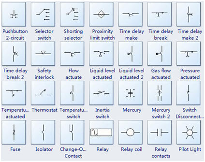
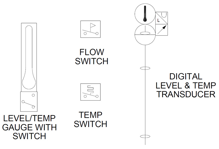
Horizontal Symbol Vertical Symbol Description HPS11 VPS11 Pressure Switch, Normally Open HPS12 VPS12 Pressure Switch, Normally Closed HTS11 VTS11 Temperature Switch 1, Normally Open HTS12 VTS12 Temperature Switch 1, Normally Closed HTS11S74 VTS11S74 Temperature Switch 3, Normally Open HTS12S74 VTS12S74 Temperature Switch 3, Normally Closed HSW21 VSW21 2nd Normally Open Contact HSW22 VSW22 2nd. The switch symbols below include SPST, SPDT, DPST, DPDT, make contact, break contact, twoway contact, 2 position switch, 3 position switch, 4 position switch, limit switch, inertia switch, mercury switch, and also delay switch such as time delay switch, time delay break, flow actuate switch, liquid level actuated switch, gas flow actuated switch, temperature actuated switch, and pressureactuated switch Also shown are the component symbols for fuse, isolator, relay contact, pilot light. Digital flow switch Cylinder, double acting, with lock Filter with auto drain Cylinder, double acting, with magnet Pneumatic Symbols DIRECTIONAL CONTROL VALVES PROCESS VALVES DESCRIPTION IMAGE DESCRIPTION IMAGE 2/2 way valve, air operated, NC Angle valve, 2way.
P&ID Symbols 2 Electrical Relay Diagram Symbols wwwindustrialtextcom ELECTRICAL RELAY DIAGRAM SYMBOLS SWITCHES Disconnect Circuit Interrupter Limit Neutral Position Circuit Breaker Normally Open Normally Closed Held Closed Held F Flow rate G User's choice Glass (sight tube) H Hand (manually initiated) I Current (electric. Symbol Description Aquastat Flow switch Pressure switch Water hammer arrester Pressure gauge with gauge cock Thermometer (specify type) Automatic air vent Valve in riser (type as specified or noted) Riser down (elbow) Riser up (elbow) Air chamber Rise or drop Branch—top connection. Generic symbol Switch SDPT A pole doublethrow Slide switch, SDPT Double Switch DPDT Doublepole, doublethrow Double Switch, DPDT Double pole double throw Multiswitch Multiswitch Multiswitch Rotary switch Rotating Multiswitch Info Multiswitch Rotating Multiswitch Multiswitch Pushbuttons / Push Switch Symbols.
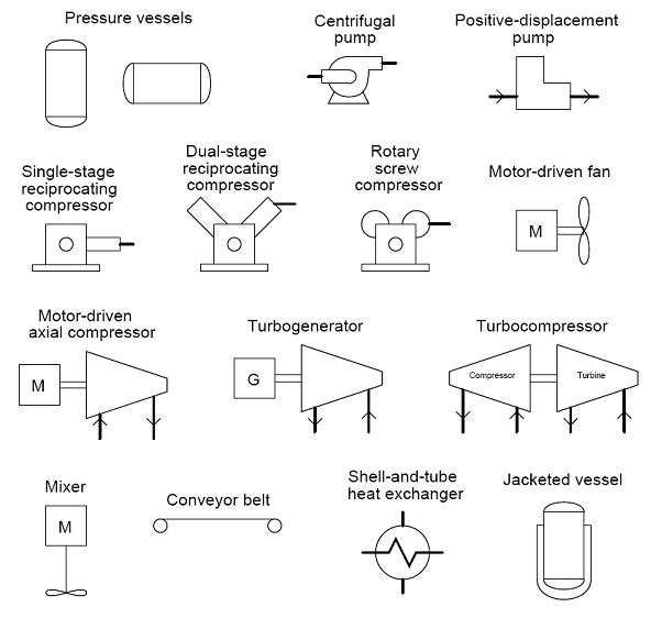
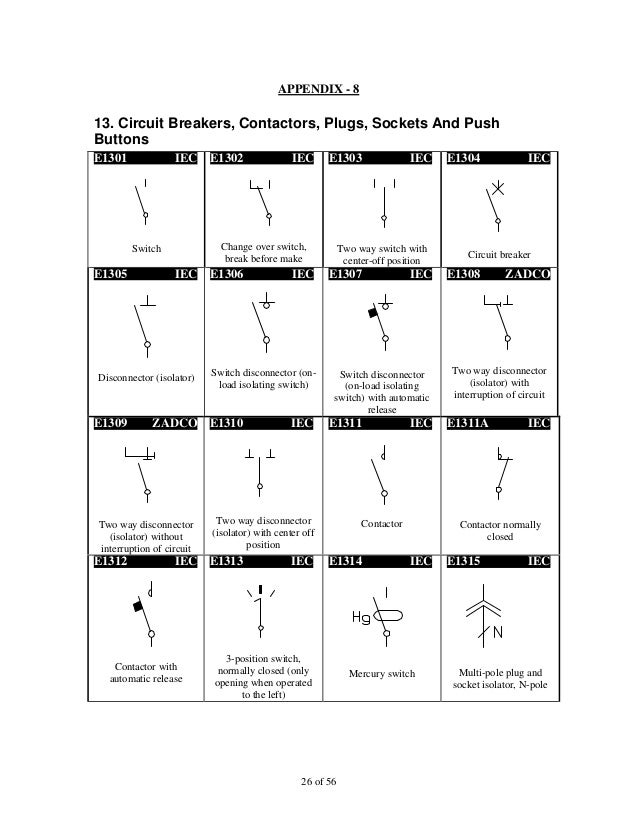
ABOUT KOBOLD USA For decades, KOBOLD has been a world leader in process measurement and control solutions We offer one of the industry’s broadest lines of sensors, switches and transmitters to measure and control flow, pressure, level and temperature. AS/NZS electrical symbols – Circuit Breakers, Switches, Contacts September 19, 19 Version 1125 Download KB File Size 1 File Count September 19, 19 Create Date June 18, Last Updated Download Description;. The symbols used in piping and Instrumentation diagrams or drawings are many and varied I have dealt with some of these symbols before but here I have given a comprehensive list of the common P&ID symbols of process equipment such as valves, flowmeters, piping line connections, and much more.
It is common to make letter combinations in PI&D diagrams according ANSI/ISA S (R 1992) "Instrumentation symbols and identification" In addition to the letter combination a succeeding number as a unique identification of the actual instrument is commonly used. Flow switch used to activate a device when flow stops When the decreasing operating flow is reached or stops the common (black wire) and the normally open (red wire) contacts open, while the common (black wire) and the normally closed (blue wire) contacts close Flow switch is used to activate a device when flow starts. SIKA flow monitors and switches monitor the flow of lowviscosity media in pipes They offer a reliable solution for ensuring the minimum flow rate and thereby protecting highquality systems and installations from damages These flow monitors and switches work on the basis of the well established.
Flow monitors and switches They offer a reliable solution for ensuring the minimum flow rate and thereby protecting highquality systems and installations from damages These flow monitors and switches work on the basis of the well established electronic and mechanical operating principles. Paddle flow switches or vane sensors with an electrical contact output are at a specific flow rate Dwyer flow switches are economical and reliable Applications include proof of boiler flow, air conditioning, controlling of dampers according to flow, and protecting pumps, motors and other equipment against low or no flow. Change the switch point (→ 6 1) Carry out high flow adjustment (→ 6 2) 3 ˜˚˛ ˜˚˛˝ ˝˙ˆˇ ˜ ˚ ˛ ˝ ˙ ˆ ˇ ˘ Your normal flow exceeds the representation range of the display (LED 9 flashes) Carry out high flow adjustment (→ 6 2) You can restore the factory setting any time (→ 7 3).
Horizontal Symbol Vertical Symbol Description HPS11 VPS11 Pressure Switch, Normally Open HPS12 VPS12 Pressure Switch, Normally Closed HTS11 VTS11 Temperature Switch 1, Normally Open HTS12 VTS12 Temperature Switch 1, Normally Closed HTS11S74 VTS11S74 Temperature Switch 3, Normally Open HTS12S74 VTS12S74 Temperature Switch 3, Normally Closed HSW21 VSW21 2nd Normally Open Contact HSW22 VSW22 2nd. Flow switch used to activate a device when flow stops When the decreasing operating flow is reached or stops the common (black wire) and the normally open (red wire) contacts open, while the common (black wire) and the normally closed (blue wire) contacts close Flow switch is used to activate a device when flow starts. If you experience any problems with the site, please contact Pete Hoffman immediately so corrections can be made Pete can be reached on campus, via email at phoffman@swtcedu or by phone at ext 2727.
Sensirion Micro Flow Switch and Bubble Detector for Liquids The LG01 liquid flow switch detects ultralow liquid flow rates or the presence of air in fluidic systems It therefore makes them more reliable The detection of liquid flows is possible within the range of a few ml/min and less The sensor's output signal of either 0 or 5 Volts indicates if the current flow rate is above or below. Digital flow switch Cylinder, double acting, with lock Filter with auto drain Cylinder, double acting, with magnet Pneumatic Symbols DIRECTIONAL CONTROL VALVES PROCESS VALVES DESCRIPTION IMAGE DESCRIPTION IMAGE 2/2 way valve, air operated, NC Angle valve, 2way. Pressure switches are in contact with the water, when you remove it water will come out (or should) NOTE Most spas are equipped with pressure switches and can be found threaded into the stainless steel heater manifold Flow switches are plumbed in line with the plumbing You can also check the pressure switch or flow switch with a an Ohm meter.
Principle Of Flow Switch Instrumentation Tools

Water Flow Sensor Air Flow Switch Liquid Flow Switch Pf3w China Digital Flow Switch For Water Flow Switch Made In China Com

Jic Standard Symbols For Electrical Ladder Diagrams Womack Machine Supply Company
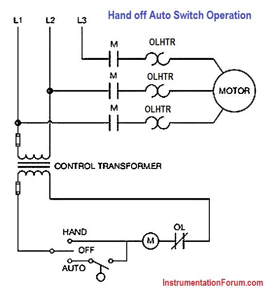
Hand Off Auto Switch Operation Electrical Engineering Instrumentation Forum

10 Common Electrical Symbols Found On Electrical Schematic Diagrams Electronic Products
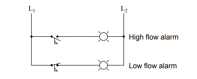
Identify High Flow Alarm And Low Flow Alarm Instrumentation Tools

Effects Switches Symbols Or Dependencies Electrical Symbols Transducers Sensor

Jic Standard Symbols For Electrical Ladder Diagrams Womack Machine Supply Company

Flow Switches And Sensors
3

Mcdonnell Miller Flow Switch Symbol Wiring Diagram Fs51 Jean Baptiste Iosca Marcella Hazan Enotecaombrerosse It
Process Flow Diagram Symbols

Instrumentation Symbols For P Id The Piping Engineering World

Reading Fluids Circuit Diagrams Hydraulic Pneumatic Symbols

Ps100 2 Pressure Type Flow Switch Manualzz
Design Elements Lamps Acoustics Measuring Instruments Electrical Symbols Thermo Electrical Symbols Switches And Relays Temperature Pressure Sensing Element Symbol

Flow Switch Cad Block And Typical Drawing

Electromagnetic Flow Meters Design And Development Embien Technologies Blog

Autocad Electrical User S Guide Overview Of Symbol Naming Conventions
Interpreting Piping And Instrumentation Diagrams Symbology Aiche

Mech23 Lecture 2 Chapter 2 Symbols And Schematics Youtube

Industrial Motor Control Symbols And Schematic Diagrams

Switches Process Actuated Circuit Schematic Symbols

Confusion About Connection Symbol To Air Flow Switch Electrical Engineering Stack Exchange
Graphical Symbol For Normally Open Held Closed Limit Switch Codes And Standards General Discussion Eng Tips

Normally Open Switch Wiring Diagram Symbols Boat Trim Gauge Wiring Diagram Begeboy Wiring Diagram Source

Flow Switches And Sensors
2
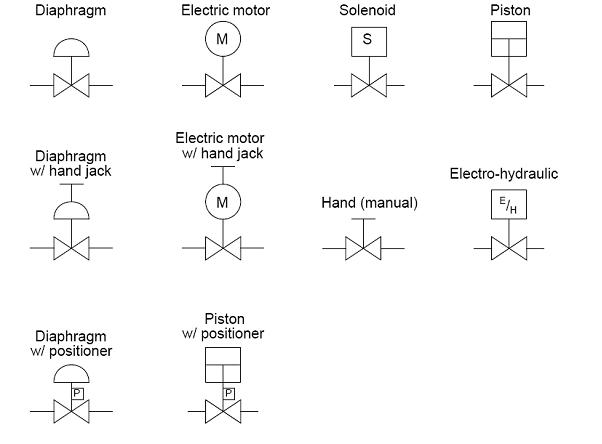
Solenoid Valve Symbols

Types Of Switches

Flow Sensors Electra Cloud Symbols

Types Of Switches Electrical Schematic Symbols Electrical Symbols Electricity
Industrial Electrical Symbols
Common P Id Symbols Used In Developing Instrumentation Diagrams Learning Instrumentation And Control Engineering

Pf3w704 03 A M 3 Color Display Digital Flow Switch For Water Pf3w Series Smc Misumi Mexico
P Id And Pfd Drawing Symbols And Legend List Pfs Pefs

Flow Sensors Electra Cloud Symbols
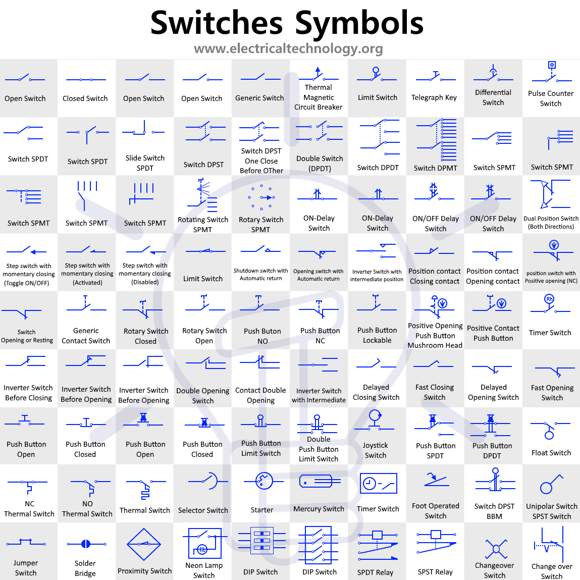
Switch And Push Button Symbols Electrical And Electronic Symbols
Chapter 4 Iso Symbols And Glossary Part 3 Hydraulics Pneumatics
Http Www Eng Auburn Edu Dbeale Mech4240 50 Microsoft powerpoint justin ovson pneumatic and hydraulic reference document Pdf

Mechanical Drawing Symbols Design Elements Hvac Equipment Building Drawing Software For Design Registers Drills And Diffusers Symbol Of Air Condition In A Circuit
Chapter 4 Iso Symbols And Glossary Part 3 Hydraulics Pneumatics
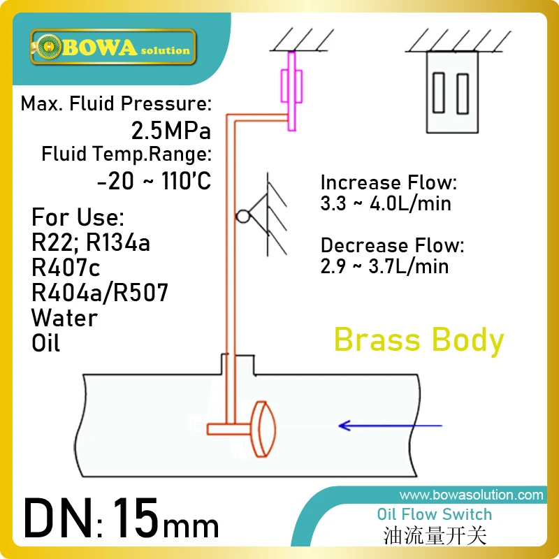
Dn15 Refrigeration Lubricant Oil Flow Switch Is Used For Screw Compressor Oil Return Pipelines To Avoid Over Or Under Flowing Oil Flow Switch Refrigeration Oilswitch Switch Aliexpress
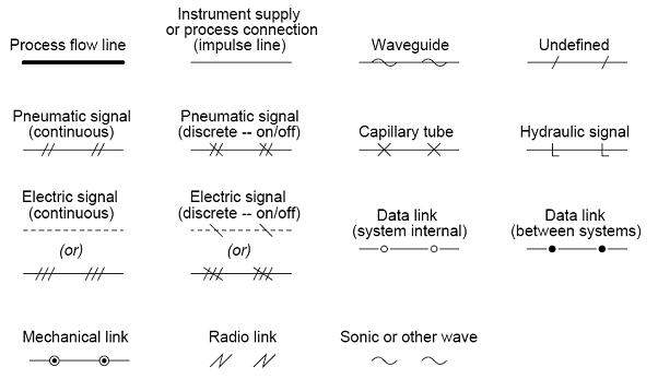
Hydraulic Symbols Piping And Tubing Symbols Normal Working Line Flexible Working Line Pilot Line Drain Line Enclosure Outline Direction Of Flow Ppt Download
Print Electrical Symbols Truncated Flashcards Easy Notecards
Hydraulic Symbology 305 Condition Monitoring Symbols
Types Of Switches
Normally Open And Normally Closed Switch Contacts Electrical Switches
Fs52 Liquid Flow Pressure Switch Water Flow Switch For Manage The Flow Changes Buy Fs52 Water Flow Switch Paddle Flow Switches Liquid Flow Switch Product On Alibaba Com

Caleffi Flow Switch Www Caleffi Com 626 Series Manualzz
Electrical Schematic Symbols Switch Jeep Cherokee Wiring Harness Begeboy Wiring Diagram Source

Common P Id Symbols Used In Developing Instrumentation Diagrams Learning Instrumentation And Control Engineering
Flow Switches And Sensors Flow Sensors Electric Equipment

Sail Switch Symbol Electrical Switches Data Flow Diagram Computer Software Electrical Wires Cable System Number Circle Transparent Background Png Clipart Hiclipart

Valve Symbols Tameson

Flow Switches And Sensors

Hydraulic Symbols Zeus Hydratech

P Ids Piping Instrumentation Diagrams And P Id Valve Symbol Library Assured Automation

Symbol Of Switches Circuit Switches Electrical Symbols

Symbol Operating Pressure Max 10 Bar Water Flow Switch Model Name Number Sr Lkb 01 Rs 750 Piece Id
Automation And Instrumentation Flow Switch
Diagram Mcdonnell Miller Flow Switch Symbol Wiring Diagram Fs51 Full Version Hd Quality Diagram Fs51 Hardwiringpa2g Atuttasosta It

P Id Symbols And Notation Lucidchart
Interpreting Piping And Instrumentation Diagrams Symbology Aiche
Common P Id Symbols Used In Developing Instrumentation Diagrams Learning Instrumentation And Control Engineering
G Maenuvabaedm
P Id Symbols Complete List Pdf Projectmaterials
Metering Symbols Electrical Symbols Pumping Solutions Inc

Triangle Tube Ccgsk07 Gasket Flow Switch Boiler Hvacdirect Com
Iec Symbol Reference

Pf2a721 03 27 Digital Flow Switch For Air Pf2a Series Smc Misumi Mexico

80 Jic Standard Graphic Symbols For Electrical Ladder Diagrams Pdf Switch Relay
2
Www Eaton Com Content Dam Eaton Products Electrical Circuit Protection Medium Voltage Vacuum Circuit Breakers Comparison Nema Iec Schematic Diagrams Mzen Pdf
Use Of Flow Meter Coowor Com

Common P Id Symbols Used In Developing Instrumentation Diagrams Learning Instrumentation And Control Engineering

Common P Id Symbols Used In Developing Instrumentation Diagrams Learning Instrumentation And Control Engineering

Flow Switches And Sensors

P Ids Piping Instrumentation Diagrams And P Id Valve Symbol Library Assured Automation
P Id Symbols Complete List Pdf Projectmaterials
P Id Symbols Complete List Pdf Projectmaterials

Hydraulics Pneumatics Plumbing F 180 Deg Flow Switch 5660 Psi Flow Switches
Q Tbn And9gcth U7t1lihak6xobvkgcku4dp1553oyo13hxaows5bvif68vdz Usqp Cau
Testbankuniv Eu Sample Understanding Motor Controls 3rd Edition Herman Test Bank Pdf
Water Flow Switch High Res Stock Images Shutterstock
Common P Id Symbols Used In Developing Instrumentation Diagrams Learning Instrumentation And Control Engineering

P Id Symbols Complete List Pdf Projectmaterials

Flow Sensors Electra Cloud Symbols
1

Solenoid Valves Discrete Control System Elements Automation Textbook
Diagram Mcdonnell Miller Flow Switch Symbol Wiring Diagram Fs51 Full Version Hd Quality Diagram Fs51 Homewiringtoolsc Giardinidelleninfe It

Typical P Id Arrangement For Pumps Enggcyclopedia
Flow Switch Symbol Free Images At Clker Com Vector Clip Art Online Royalty Free Public Domain

Hydraulic Symbology 301 Electrical And Electronic Symbols

Mechanical And Plumbing Symbols And Abbreviations Cad Block And Typical Drawing
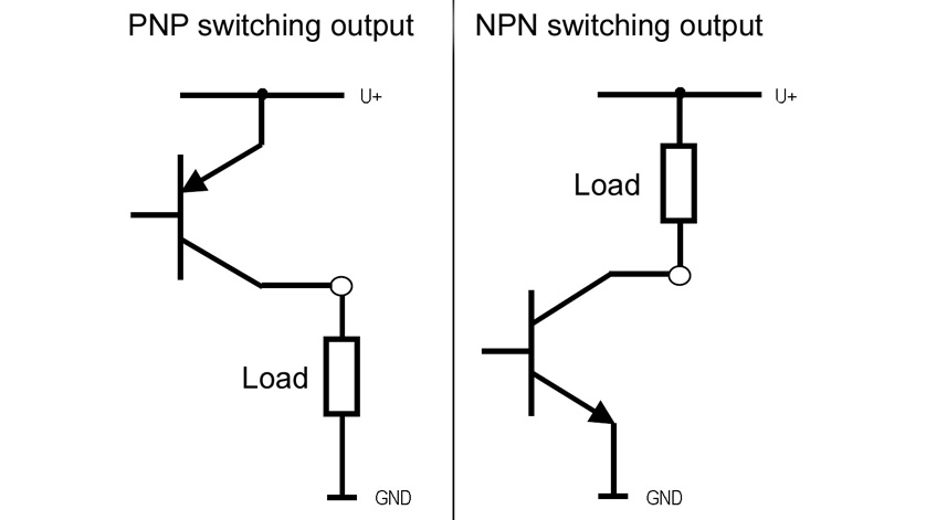
Connection Diagram Of Pnp And Npn Transistor Outputs For Electronic Pressure Switches Wika Blog

P Id Common Symbols How To Read A P Id Instrumentation And Control Engineering

Hvac About Stout Mep


